Radio
“Hardware: the parts of a computer that can be kicked.”
— Jeff Pesis
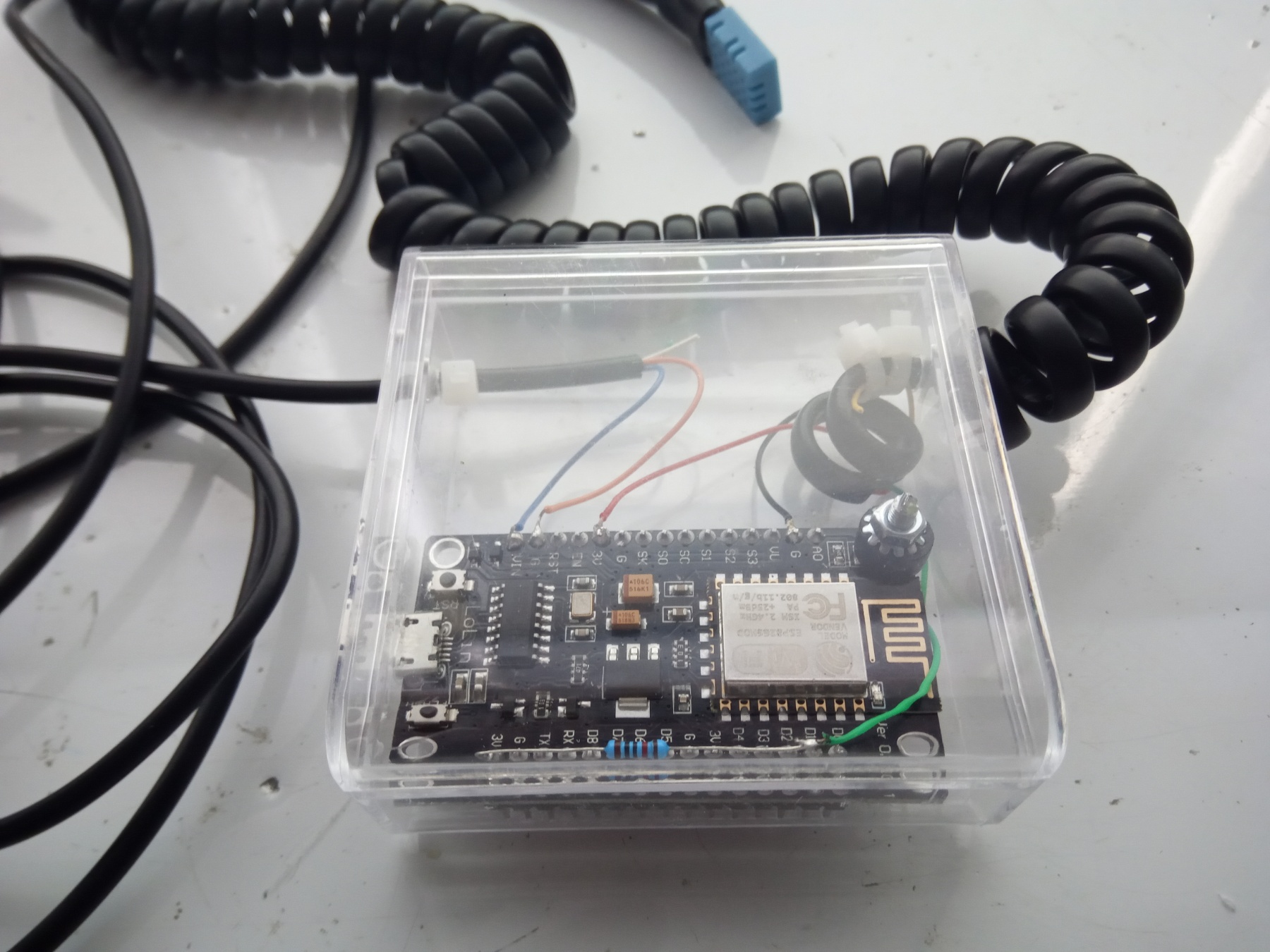
Monitoring temperature and humidity in server rooms are usually tasks for dedicated hardware and software. It is just a case of this stupid COVID situation that called for urgent and somewhat desperate measures. Postal services are not functioning normally, delivery time for everything is uncertain and some things are even impossible to buy. Combined with living in a godforsaken place it`s as Chris Rea would say a “Road to Hell”. This is why I went down this road and put Domoticz and ESP to the task and created DIY server room monitoring and alerting system.
I will try to make this look more like a guide since there is plenty of applications for this kind of device.
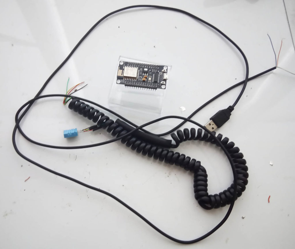
I made this as simple as it can be. I combined the ESP8266 development board with a DHT11 temperature and humidity sensor. It`s what I had at my disposal, maybe in a different situation, I would use DHT21 or BME280 sensor. Here is a schematic:

This is as easy as it can be no need for any explanation except power connections. You can supply power like this or simply use a built-in USB connector on the ESP board. I just put a standard USB connector on the other side so it can draw power from any USB port. I chose this method since I did not want any possibility for data communication if the USB is plugged to a port on the server or something like that.
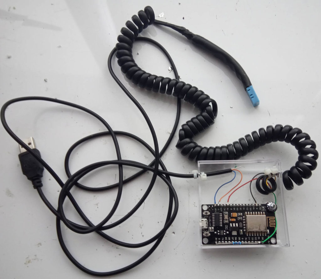
It took 30 minutes to put everything together. Measuring part of the DIY server room monitoring system is finished.
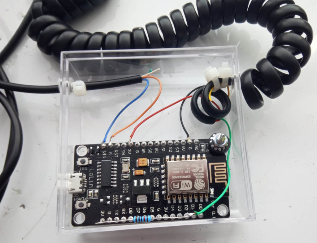
I did not use any extra circuit board since there is only few wires and one resistor. ESP board was big enough to host everything.
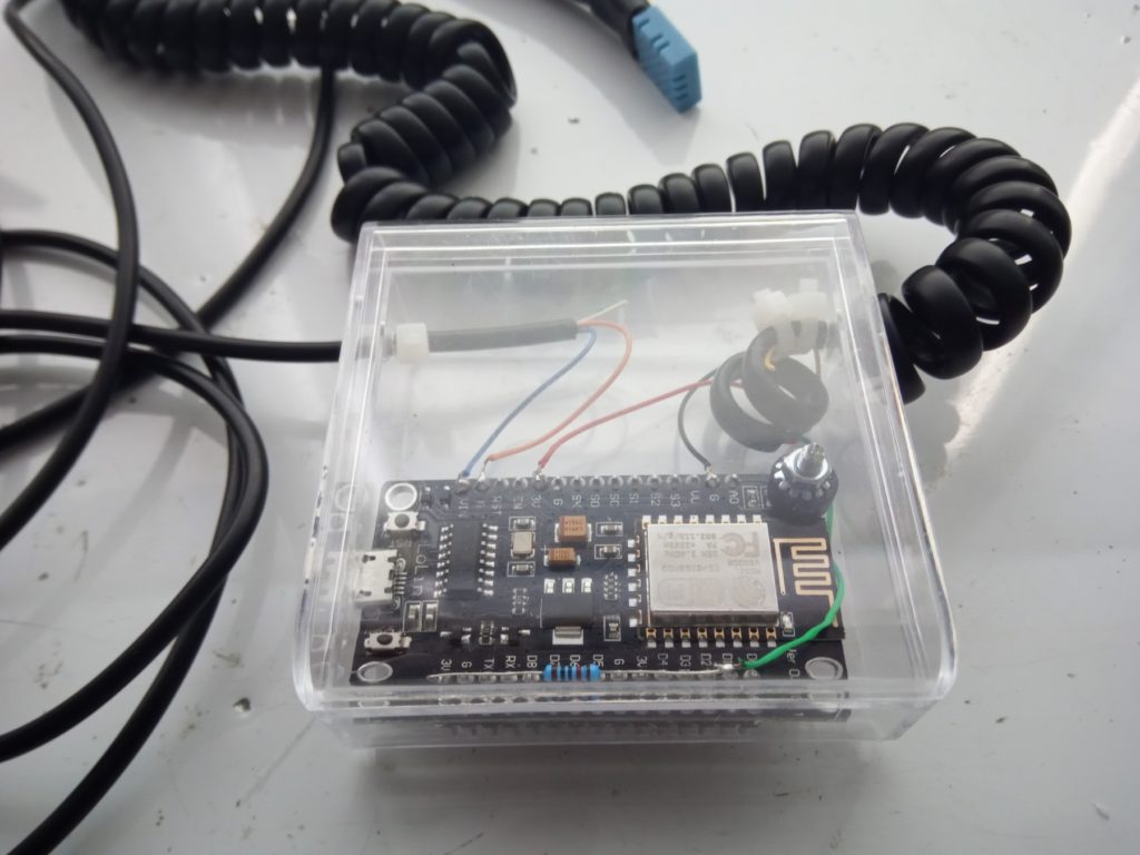
At the end I found a transparent box that some kind of hdmi adapter came in and used it as a casing. It fitted perfectly.
I already wrote here about flashing Tasmota on ESP but I will mention it again. First, get your hands on Tasmota Pyflasher and Tasmota firmware. You will want to use the tasmota-sensors.bin file. That is the only one you need in this type of flashing. Second, connect your esp to your computer and press reset while holding the flash button.
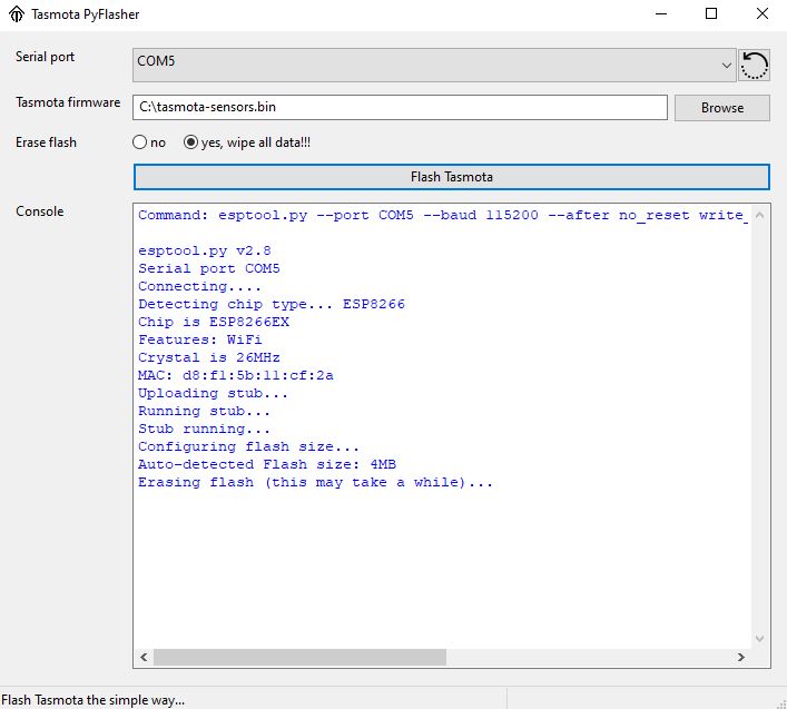
First point flasher to the location of the .bin file and chose com port number that your ESP uses. Second, hit “Flash Tasmota”.
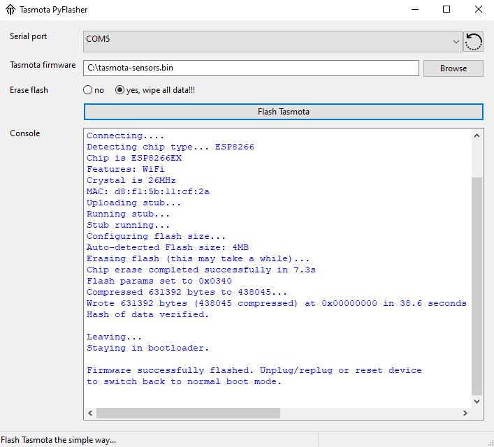
It should soon report that firmware was successfully flashed and that`s all regarding flashing.
Scan for Wi-Fi networks on your mobile phone. You should see a new SSID with a tasmota_something in its name. When connected to that network, you will get a prompt to sign in. Click sign in and you will get a prompt to enter SSID and password of your network. It will look like the picture below, and it is as simple as it can be.
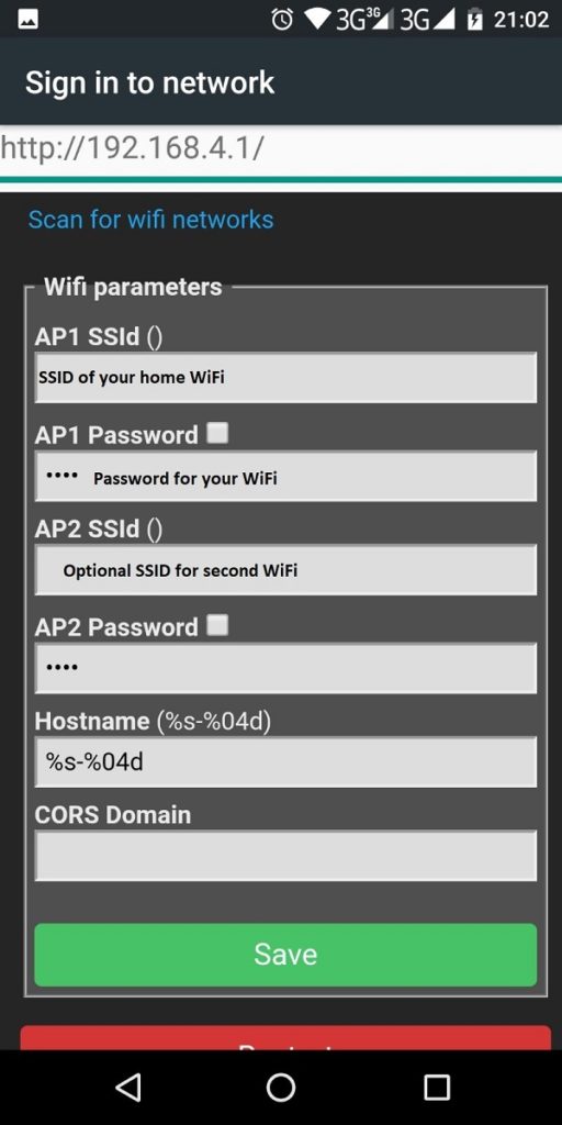
First, take note that ESP supports only 2.4 GHz networks. Therefore make sure that your network is 2.4 and not only 5 GHz. Second, if you have two Wi-Fi networks you can also configure the other one as a failover.
Now your device is connected to Wi-Fi. Therefore go to your DHCP server and check what IP address is leased to your Tasmota device.
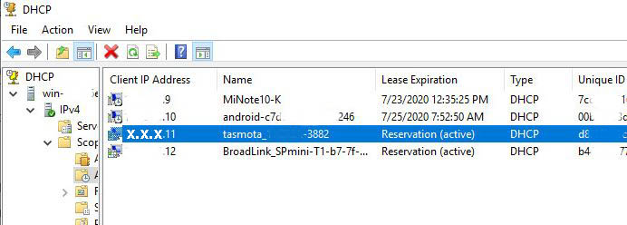
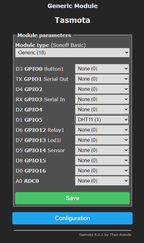
Afterwards, enter that address to a browser on the device that is on the same network and you should get the Tasmota web interface. Click on configuration and then configure the module. Under Module type, chose Generic(18). Since we connected DHT11 to D1 open the options next to D1 GPIO5 and find and select DHT11(1). Click Save, and go back to configuration.
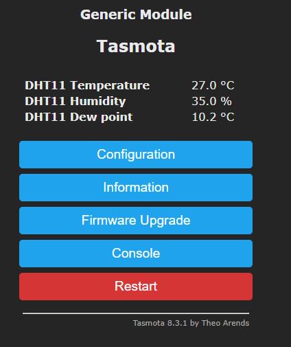
Now you should see readings from sensor on the main Tasmota page.
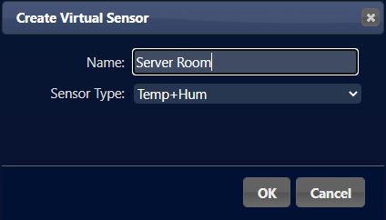
From here we go under the assumption that there is Domoticz up and running. If not, here is the full guide for the setup. On the Domoticz go to Setup -> Hardware and Create Virtual Sensors. (If you already do not have a Dummy virtual switch, create one now).


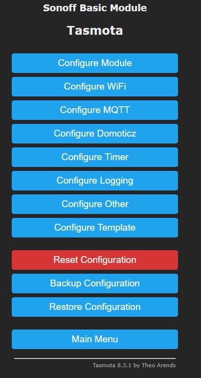
Now back to Tasmota again. We need to configure it to use MQTT and Domoticz. So under configuration, we first go to Configure MQTT and after that to Configure Domoticz.
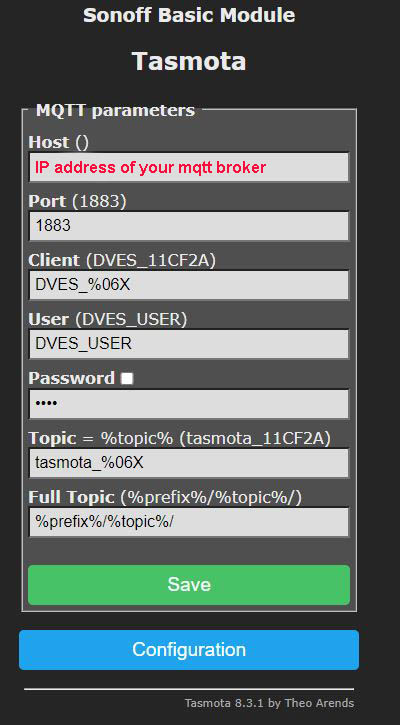
In the Configure MQTT, under Host() field type the IP address of your mqtt broker. In most cases it will be on the same machine as Domotics. Therefore it will also be the same IP address.
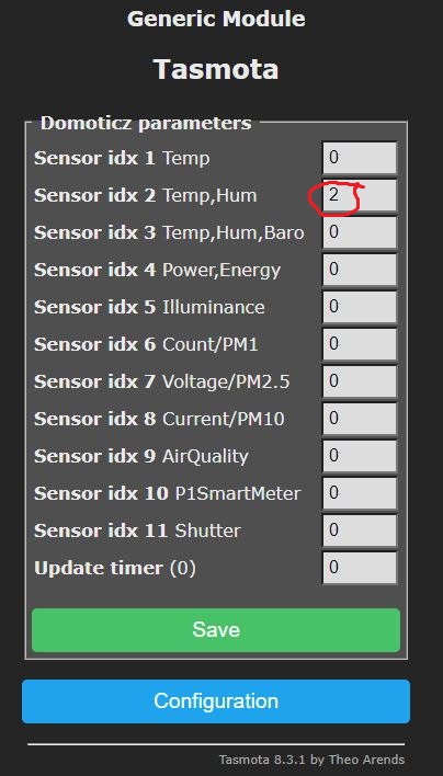
At this time, we go to the Configure Domoticz menu and if you remember the moment when we created the virtual sensor on Domoticz, now we need its idx. In our case it was 2, therefore we will enter number 2 under Sensor idx 2 Temp,Hum field. Certainly, here is just a coincidence that Sensor idx 2 Temp and the number 2 that we got from Domoticz are the same. For instance, if it were the next sensor created on this Domoticz instance it would be Sensor idx 2 Temp,Hum 3.

Here we can see how it looks like in Domoticz. Not bad ha? 🙂 Besides that, the real power of this is in notifications. Notification settings look like this.

So it will send an email and Telegram message if the temperature exceeds 25 degrees Celsius. Not to enter in explanations why this temp as a trigger, let`s just say that it does a great job for me at this moment. And here is how 24-hour log looks like so you will figure out one of the reasons why I made all this in the first place.

For instance in this situation it was necessary to log and visualize data to find the problem, and to be able to document it. Therefore, this little project just did that, and in the end, it will stay, as it proved to be quite useful.
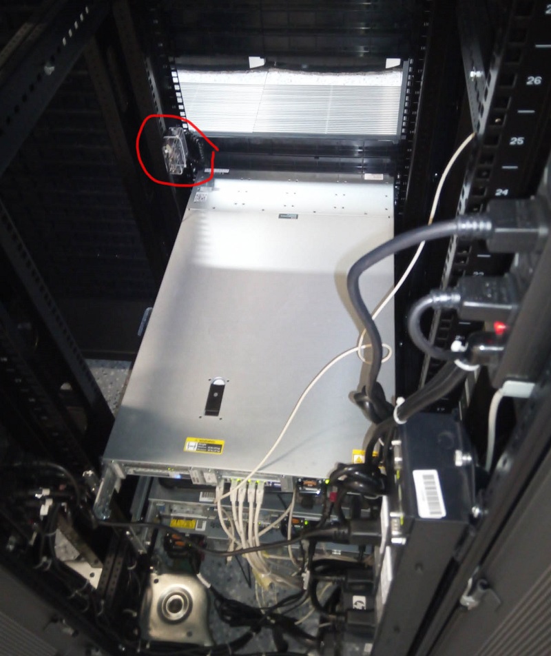
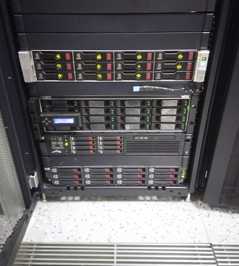
Likewise, here are few more pictures of two devices that I made to just be plugged in the AC utility socket and transmit temperature and humidity. For instance, I used adapters of the old cellphones as a power source and put ESP on top of it with DHT21 outside to avoid it being influenced by the heat that adapter and esp produce.
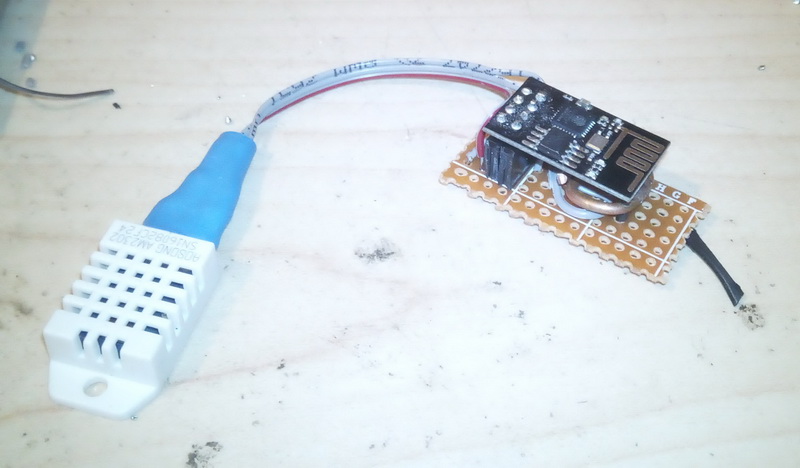
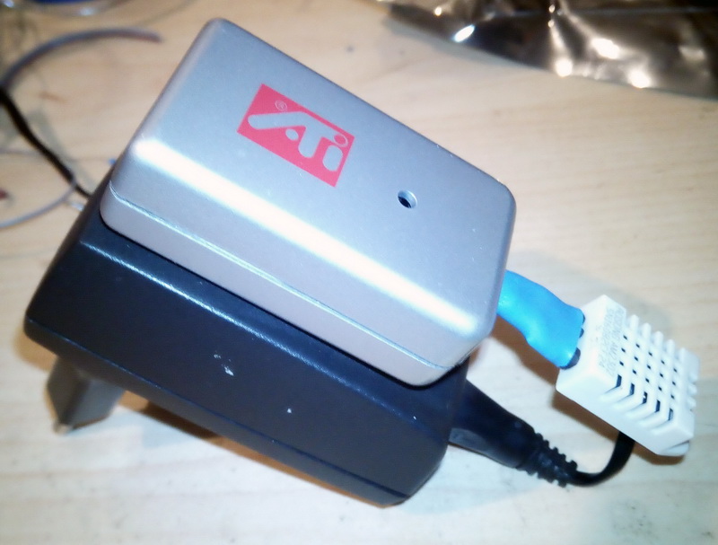

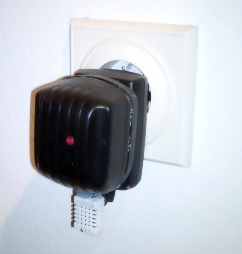
Once more, thank you for reading.

Posted in *.*, DIY, Home Automation Tagged with: Domoticz, ESP8266, server room monitoring, Tasmota