

How it started…
My love for technology and electronics eventually led me to the Amateur Radio hobby, which is the beginning of this article. Long story short, I got my license and call sign E70BS, purchased my first rig (Yaesu FT991A), and needed a PSU. So it led to designing and making my Linear PSU for Radio.
Computer PSU for HAM Radio
At first, I used a Chieftec computer PSU declared at 40 Amps on a 12V Rail. I stripped it of all unnecessary wires and used the ones for GPU with 2×8 pin connectors to feed my radio. It works great but the radio is not able to produce full RF output power while working on 12V. I did not want to force the PSU to 13.8, as I had some bad experiences with those modifications. Half-volt or something like that would be fine, but here we talk about more than a 10 % voltage rise. I do not say that it can`t be done, just decided to take a different path.
E70BS Linear PSU for Radio
I made quite a few classic PSUs in the past. I know that we are long in the era of switching PSUs, but I like to have a classic power source with a big good old transformer for some uses.
And I like to make things, there is a big joy when you create something nice. I decided to make a power supply that would be as stable as possible, protect the radio from overvoltage, and minimize any potential interference that could come from the PSU. Another project constraint was to use as much as possible parts that I already had. That included a box from an old ECG machine, a transformer, capacitors, a heatsink with power transistors, and some more parts. You know, the usual stuff that you have lying around the house 🙂
Project phases
I divided this project into two phases. The first one is the PSU itself, transformer, rectifier, and capacitors, with stabilization and overvoltage protection. The second one is for control and measuring to make it a little bit modern and nice looking.
Phase one
Voltage stabilisation
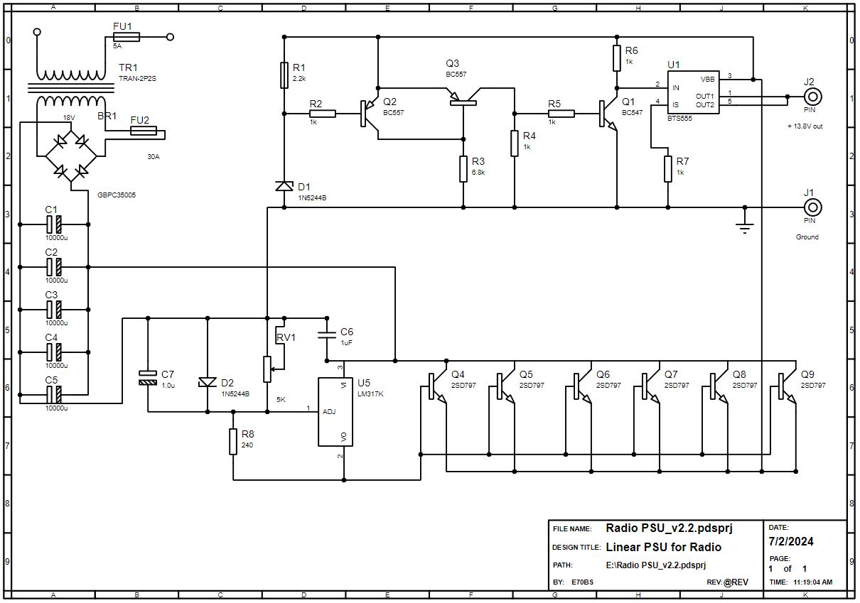
I had a transformer with an output of 16V and rectified it with 35A Graetz and 50000 micro Farads capacitors. After that is a good old LM317 voltage regulator driving 6 2SD797 in parallel. I did not put emitter resistors at the end, since I wanted to avoid voltage drop, and my transistors were matched. There is a ten-turn 5K trimmer RV1 that is for adjusting the output voltage. D2 is a 14V Zenner diode and it is preventing to turn RV1 over 14 volts.
Overvoltage protection
First try…
This part is something that took most of my time to design. At first, I tried to make this with the FQP47P06 P channel FET but had a 2V voltage drop of D-S with two of them in parallel and with a 20A load. I experimented later with increasing G-S voltage, but the drop was the same even though gates were supposed to be fully opened. This was a show-stopper. I think I got some fake FQP47P06 FETs.
Second shoot…
Then a friend of mine, Zoran E76C told me about BTS555 and I decided to give it a shoot. It is used in the automotive industry and has a load current of 165A and On-State resistance of 2.5 mOhm. After reading its datasheet I adjusted the circuitry that I used to control those bloody P-Channel FETs, and that did the job. Long story short transistors Q1 to Q3 with D1 Zenner diode of 14V work to close U1 BTS555 in case of the overvoltage. In this setup, it will cut off the output if the input gets over 14.5V. This is for protecting the radio in case the stabilization part blows and prevents it from delivering 22V DC from the rectifier bridge directly to the radio. I tested this as much as I could and it works like a charm. It`s a neat thing to have, just in case.
Phase two
Arduino Nano and Fan Speed control
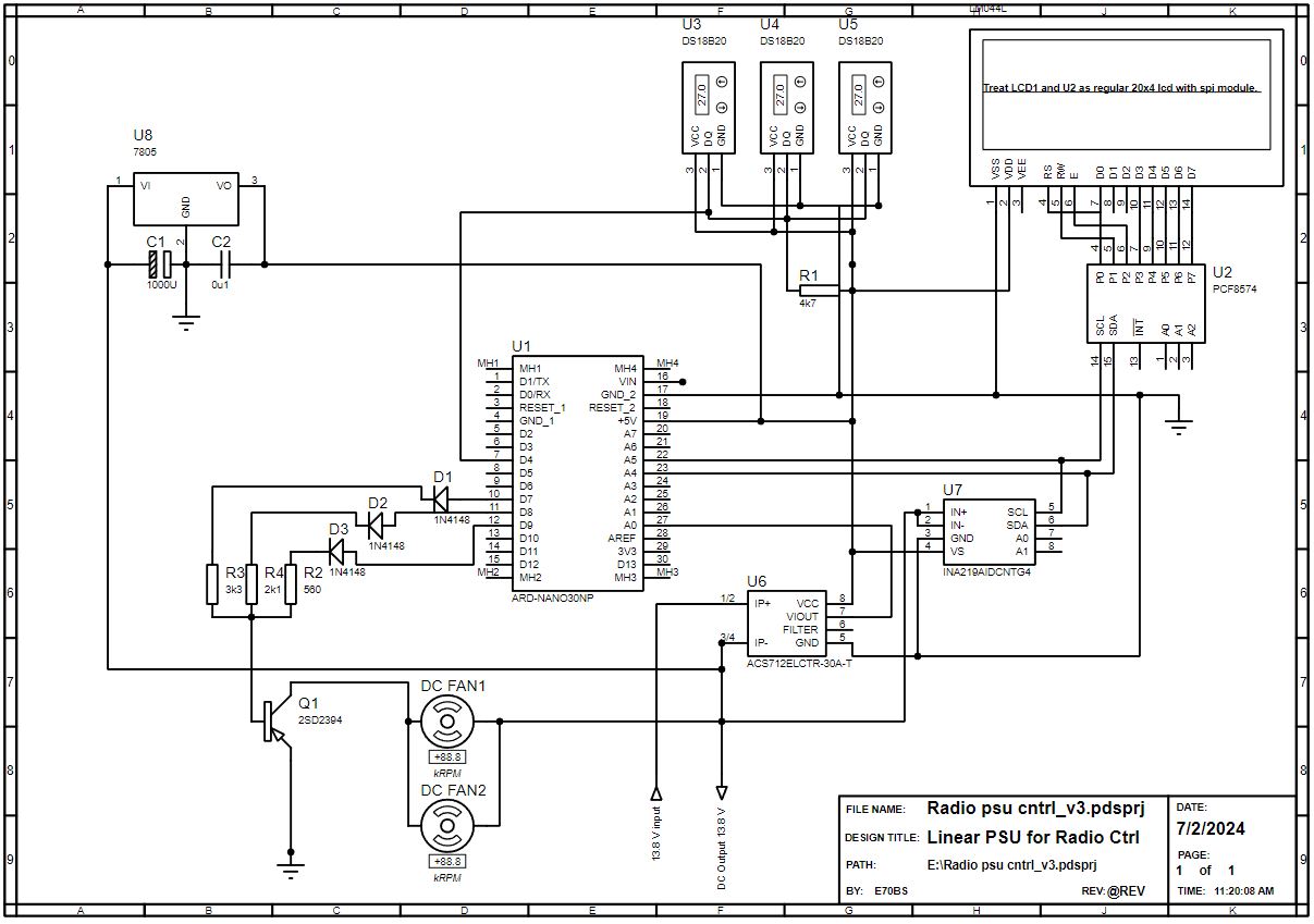
I did not have a decent Arduino Nano and display elements for the Proteus so the schematic may look weird, but you will get the point. I used 3 Dallas DS18B20 sensors for temperature measuring. Two for different zones on the heatsink tunnel for power transistors, and the third for the rectifier bridge temperature. I use readings from U3 and U4 to control the speed of the fans. In dependence on the temperature, Arduino outputs D7, D8, and D9 go to a high state and open the Q1 transistor more or less so it is a way to have three different Fan speeds. You will maybe ask why so complicated way, why not PWM? Well, I had cases where PWM was making some nasty noise, or to call it disturbances, or QRM so I decided to avoid use of it here.
Current and Voltage sensors
I used an INA219 voltage and a current sensor for voltage measuring. It is easy to use, has its own Arduino library, and is very precise in voltage measuring. It is capable of measuring current also for up to 3A but I did not manage to adjust the shunt resistor and code accordingly to get even satisfactory precise measurement at 30 Amps current. Not to mention a shunt big enough to hold that kind of current. So for that purpose, I moved to the ACS712ELCTR-30A-T Hall effect sensor. I must say that I`m very satisfied with it, although I was skeptical regarding its pins size compared to the 30A current that it is supposed to handle.
Arduino code
I did not clean up a code, and I`m not a code guru so do not expect miracles here 🙂 I used some parts that I found online, and if I missed giving some credits, sorry. I think it is commented enough not to cause you any trouble if you decide to make your version of PSU.
// code for  E70BS Linear PSU for Radio
// Firmware version 1.6.3
#include <Wire.h>
#include <Adafruit_INA219.h>
#include <LiquidCrystal_I2C.h>
#include <OneWire.h>
#include <DallasTemperature.h>

// Set the LCD address to 0x27 (or 0x3F) for a 16 chars and 2 line display
//LiquidCrystal_I2C lcd(0x27, 16, 2);
LiquidCrystal_I2C lcd(0x27, 20, 4);       //If using a 20 x 4 display, uncomment this line and comment out the line above

// Data wire is plugged into pin 4 on the Arduino
#define ONE_WIRE_BUS 4
// initialize the library by associating any needed LCD interface pin
// with the arduino pin number it is connected to
// const int rs = 12, en = 11, d4 = 5, d5 = 4, d6 = 3, d7 = 2;

OneWire oneWire(ONE_WIRE_BUS);


DallasTemperature sensors(&oneWire);
byte nextSensor = 0;
byte const numSensors = 3;
byte Address[numSensors][8];
byte sensorCount;
DeviceAddress Probe01 = { 0x28, 0xCD, 0x02, 0x3B, 0x05, 0x00, 0x00, 0xA1 };
DeviceAddress Probe02 = { 0x28, 0xFF, 0xDD, 0x5B, 0x85, 0x16, 0x05, 0x98 };
DeviceAddress Probe03 = { 0x28, 0x44, 0x06, 0x3B, 0x05, 0x00, 0x00, 0xC2 };

float shuntMultiplier = 0.022;
Adafruit_INA219 ina219;
unsigned int x = 0; //for acs712 hall current sensor
float AbsI = 0;
//temp settings for fan speeds
  float tempon1 = 45.00;
  float tempon2 = 53.00;
  float tempon3 = 60.00;
  bool logA = false;
//end of temp settings for fan speeds
  float Temp1;
  float Temp2;
  float Temp3;
  //test
  int varSpeed;
 //end test
float a;

//These 5 arrays paint the bars that go across the screen.
byte zero[] = {
  B00000,
  B00000,
  B00000,
  B00000,
  B00000,
  B00000,
  B00000,
  B00000
};
byte one[] = {
  B10000,
  B10000,
  B10000,
  B10000,
  B10000,
  B10000,
  B10000,
  B10000
};

byte two[] = {
  B11000,
  B11000,
  B11000,
  B11000,
  B11000,
  B11000,
  B11000,
  B11000
};

byte three[] = {
  B11100,
  B11100,
  B11100,
  B11100,
  B11100,
  B11100,
  B11100,
  B11100
};

byte four[] = {
  B11110,
  B11110,
  B11110,
  B11110,
  B11110,
  B11110,
  B11110,
  B11110
};

byte five[] = {
  B11111,
  B11111,
  B11111,
  B11111,
  B11111,
  B11111,
  B11111,
  B11111
};

long randNumber;
  int speed1 = 7;
  int speed2 = 8;
  int speed3 = 9;
void setup(void)
{
  pinMode(speed1, OUTPUT);
  pinMode(speed2, OUTPUT);
  pinMode(speed3, OUTPUT);

  Serial.begin(9600);
  lcd.init();
  lcd.clear();
  lcd.backlight();      // Make sure backlight is on
  sensors.setResolution(Probe01, 10);
  sensors.setResolution(Probe02, 10);
  sensors.setResolution(Probe03, 10);

  sensors.begin();
  //bool setMaxCurrentShunt(float ampere = 20.0, float ohm = 0.002);
  uint32_t currentFrequency;

  // Initialize the INA219.
  // By default the initialization will use the largest range (32V, 2A).  However
  // you can call a setCalibration function to change this range (see comments).
  if (! ina219.begin())
  {
    lcd.display();
    lcd.setCursor(0, 0); // top left
    lcd.print("Failed to find INA219 chip");

    while (1) {
      delay(10);
    }
  }
  // To use a slightly lower 32V, 1A range (higher precision on amps):
  //ina219.setCalibration_32V_1A();
  // Or to use a lower 16V, 400mA range (higher precision on volts and amps):
  //ina219.setCalibration_16V_400mA();
  sensorCount = sensors.getDeviceCount();
  oneWire.reset_search();
  for (byte i = 0; i < sensorCount; i++)
  {
    // assigns the next address found to Address[i][0..7]
    if (!oneWire.search(Address[i]))
    {
      Serial.print("Unable to find address");
      Serial.print("\n");
    }
  }

  // initialize the LCD and allocate the 5 arrays to a number.
  lcd.init();
  lcd.backlight();
  lcd.createChar(0, zero);
  lcd.createChar(1, one);
  lcd.createChar(2, two);
  lcd.createChar(3, three);
  lcd.createChar(4, four);
  lcd.createChar(5, five);
introFunction();
lcd.clear();
}

void loop(void)
{

 Temp1 = sensors.getTempC(Probe01);
 Temp2 = sensors.getTempC(Probe02);
 Temp3 = sensors.getTempC(Probe03);

  sensors.requestTemperatures();
  float shuntvoltage = 0;
  float busvoltage = 0;
  float current_mA = 0;
  float loadvoltage = 0;
  float power_mW = 0;
  float shuntCurrent_A = 0;
  float absloadvoltage = 0;
  float absshuntCurrent_A = 0;
  shuntvoltage = ina219.getShuntVoltage_mV();
  busvoltage = ina219.getBusVoltage_V();
  current_mA = ina219.getCurrent_mA();
  power_mW = ina219.getPower_mW();

  loadvoltage = busvoltage + (shuntvoltage / 1000);
  absloadvoltage = abs(loadvoltage);
  current_mA = ina219.getCurrent_mA();
  shuntCurrent_A = current_mA * shuntMultiplier;
  absshuntCurrent_A = abs(shuntCurrent_A);


  float AcsValue = 0.0, Samples = 0.0, AvgAcs = 0.0, AcsValueF = 0.0;

  for (int x = 0; x < 150; x++) { //Get 150 samples
    AcsValue = analogRead(A0);     //Read current sensor values
    Samples = Samples + AcsValue;  //Add samples together
    delay (3); // let ADC settle before next sample 3ms
  }
  AvgAcs = Samples / 150.0; //Taking Average of Samples

  AcsValueF = (2.5 - (AvgAcs * (5.0 / 1024.0)) ) / 0.066;
 float AcsValueG;
  if (AcsValueF < 0.2)
  {
    AcsValueG = 0;
  }
  else
  {
    AcsValueG = AcsValueF;
    }

  AbsI = abs(AcsValueG);

  // code credits to https://www.engineersgarage.com/acs712-current-sensor-with-arduino/

  lcd.display();
  lcd.setCursor(0, 0); // top left
  lcd.setCursor(0, 0);
  lcd.print("T1=");
  lcd.print(Temp1, 0);
  lcd.print("C");
  lcd.print(" ");
  lcd.setCursor(7, 0);
  lcd.print("T2=");
  lcd.print(Temp2, 0);
  lcd.print("C");
  lcd.print(" ");
  lcd.setCursor(14, 0);
  lcd.print("T3=");
  lcd.print(Temp3, 0);
  lcd.print("C");
  if(Temp2 <10){
  lcd.print(" ");
    }

    lcd.setCursor(0,2);
    lcd.print("I=");
    lcd.print(AbsI);
    lcd.print("A");
    lcd.print(" ");
    lcd.setCursor(10, 2);
    lcd.print("U=");
    lcd.print(absloadvoltage, 2);
    lcd.print("V");
    if(absloadvoltage <10){
    lcd.print(" ");
    }
    updateProgressBar(AbsI, 30, 3);

setSpeed();

}

 void setSpeed()

 {

 if (Temp1 > tempon3 || Temp2 > tempon3)
{
//  varSpeed = 3;
  digitalWrite(speed1, HIGH);
  digitalWrite(speed2, HIGH);
  digitalWrite(speed3, HIGH);
  }
else  if (Temp1 > tempon2 || Temp2 > tempon2)
{
//  varSpeed = 2;
  digitalWrite(speed1, LOW);
  digitalWrite(speed2, HIGH);
  digitalWrite(speed3, LOW);
  }
 else  if (Temp1 > tempon1 || Temp2 > tempon1)
{
//  varSpeed = 1;
  digitalWrite(speed1, HIGH);
  digitalWrite(speed2, LOW);
  digitalWrite(speed3, LOW);
    logA = true;
  }

else  if ((Temp1 < tempon1 || Temp2 < tempon1) && logA == false)
{
//  varSpeed = 0;
  digitalWrite(speed1, LOW);
  digitalWrite(speed2, LOW);
  digitalWrite(speed3, LOW);

  }

     else if (Temp1 < tempon1 -6  || Temp2 < tempon1 - 4)
  {
  digitalWrite(speed1, LOW);
  digitalWrite(speed2, LOW);
  digitalWrite(speed3, LOW);
  logA = false;
    }
  }

 void introFunction()
 {
  digitalWrite(speed1, HIGH);
  lcd.setCursor(0, 0);
  lcd.print("Linear Power Supply");
  delay(5000);
  lcd.setCursor(1, 1);
  lcd.print("Designed by E70BS");
  digitalWrite(speed1, LOW);
  digitalWrite(speed2, HIGH);
  delay(3000);
  lcd.setCursor(1, 2);
  lcd.print("  Firmware 1.6.3");
  delay(3000);
  digitalWrite(speed2, LOW);
  digitalWrite(speed3, HIGH);
  lcd.setCursor(8, 3);
  lcd.print("\"73\"");
  delay(3000);
  digitalWrite(speed1, LOW);
  digitalWrite(speed2, LOW);
  digitalWrite(speed3, LOW);


  }
 void updateProgressBar(unsigned long count, unsigned long totalCount, int lineToPrintOn)
 {

    double factor = totalCount/100.0;
    int percent = (count+1)/factor;
    int number = percent/5;
    int remainder = percent%5;
    if(number > 0)
    {
      for(int j = 0; j < number; j++)
      {
        lcd.setCursor(j,lineToPrintOn);
       lcd.write(5);
      }
    }
       lcd.setCursor(number,lineToPrintOn);
       lcd.write(remainder);
     if(number < 20)
    {
      for(int j = number+1; j <= 19; j++)
      {
        lcd.setCursor(j,lineToPrintOn);
       lcd.write(0);
      }
    }
 }
I will not comment on the code much. Just to mention, you will need to change Probe01 – Probe03 addresses to match your Dallas DS18B20 sensor addresses. The rest of the code should be generic. My power transistors are on the heatsink with an air tunnel, and I set:
float tempon1 = 45.00;
float tempon2 = 53.00;
float tempon3 = 60.00;
to match my setup. If you have another heatsink solution, you may want to adjust these differently, or you may even not need fans. When my radio is at RX fans do not turn on, and when in mixed RX/TX mode they will go to speed one, sometimes to speed two depending on room temperature and the power setting of the radio.
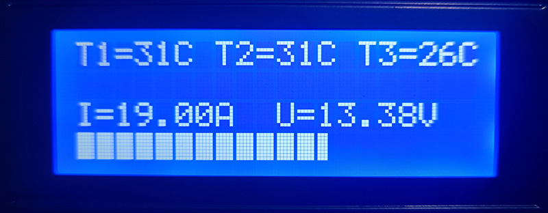
Display
I must say that FT-991A is quite power-hungry, it consumes up to 20A depending on mode, band, and power setting. It is convenient to see power consumption on the PSU. I got used to that feature and I like it.
Testing
Before even connecting a radio to PSU it had to pass some tests until I was happy with it. The main one was to keep it under descent load for some time to see how it behaved. After burning a few quite big resistors I found part of an electric heater that did the job as a dummy load. The heater wire got red but it handled 22 amps for an hour. This was enough for me as the radio is never in TX the whole time, and this proved that cooling and construction are good enough.
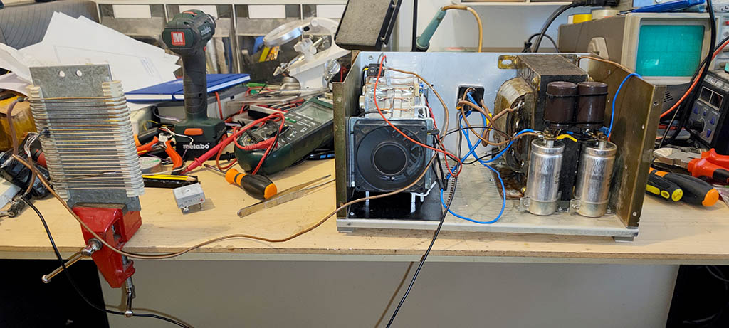
Making of E70BS Linear PSU for Radio
I was photographing the whole process and here is the gallery that shows the making of the PSU from start to finish. It took me almost a year from the idea to the finished device, but I`m happy with the result.


Conclusion
I have been using this PSU for a year now. It works like a charm. I really like to see the power consumption on the display, and a power bar on the display line 4 is very neat. I added two XT60 connectors to the front, and they are a great addition when you need to power up something else besides the radio. Anyway, XT60s can handle even the radios consumption, so I think they are a good choice. I also made a USB connection to Arduino available on the back, so I can upgrade the firmware as needed without opening the PSU. Overall, I think this project was nothing but a complete success. It is nice, not too big for its power and features, and most of all it is reliable and homemade. If I continue this way I will begin to sound like Gollum … My own my precious 🙂
Here are a few photographs of the finished device and my humble radio shack.


E73CV Dual Power supply
My friend Stevo E73CV, made another variation of this PSU. He had a little bit different needs so he combined this design In a little bit smaller version with switching PSU. Here I thank him for the pictures. This is another beautiful handmade piece of engineering.
Here is the result:


If You like this article maybe you would like to see the one about making a 250W Dummy load.
Thank you for reading and if you have any questions or want to make E70BS Linear PSU for Radio and need help, please leave a comment and I will try to respond as soon as possible.
73,
E70BS