
How does monitoring Temperature, Humidity, Pressure, Illuminance, and Air quality sounds like? Well, it sounds great especially if we can do it in under 50 US $ budget, and it even has some basic weather prediction functions, when combined with Tasmota and Domoticz.
Why measure air quality?
We had a situation in the city where people started to get sick with respiratory problems at the mass level and it was obvious that a major problem is the quality of the air. I mean it was noticeable with the bare eyes and nouse but authorities kept saying that air is ok, and they were publishing fake results. Moreover, results were in the form of a statement like “Air quality is at a satisfactory level”. Yes, it is ok if you ar an internal combustion engine with a great air intake filter!
How could air become so bad in a city without industry?
This started happening with the beginning of a heating season, and it was just a coincidence that the city got a brand new heating plant. Well, later we find out that it was not exactly in city ownership. Moreover it is a privately owned and operated, with a nice and lucrative contract. In fact, the new plant is so nice that they shut down former plant (with chimneys like two times higher than those at the new plant) that was owned by the city and the only heating option left is this new monster that uses wood as a fuel. I could write a completely new story on this subject, but I will stop here.
Why Nova SDS011 PM sensor?
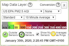
I came to learn about it from the necessity. I wanted to see what is going on with the air pollution and I found a bunch of sensors there on the market but did not know where to start. In fact, one independent journalist brought few “Purple Air” sensors and installed them around the city, and the results were catastrophic. For example, they measured 300 – 500 (US EPA PM2.5 AQI ) almost all the time for 2 months. On the other hand, 0 – 50 is ok on their scale and that scale ends with 500.
These purple air sensors cost around 250 US $ so they are not so cheap. On the other hand, you just have to put it on a good spot, connect it to Wi-Fi and power. But it is very enjoyable to build something yourself so, DIY again 🙂 . Just one more comment, authorities said that these “so-called” measuring devices like “Purple Air” sensors are not calibrated, and not attested by their accredited agency so the results were wrong. As soon as they started talking things like that, the air became so pure and enjoyable to breathe that everyone was so shocked and happy to have the opportunity to live under so wise rule.
Joost Wesseling (RIVM) – Air quality measurements using cheap sensors
What convinced me even more that I`m on the right track was Mr. Joost Wesseling from The Netherlands National Institute for Public Health and the Environment, keynote at the Things conference in Amsterdam. If you read this article until now, it means you are interested and I warmly suggest you watch this 25-minute video https://www.youtube.com/watch?v=FgvghFFSQ6c .
Back to technical stuff…
First, we will make a little bom (bill of materials) containing major parts. After all, we are building a quite complex device. Therefore we must know what parts do we need.
| Part | Price US $ |
| 1. ESP8266 development board | 2.8 |
| 2. Nova PM sensor SDS011 High precision laser pm2.5 air quality detection sensor module | 18 |
| 3. BME280 temp hum baro sensor 3V | 3 |
| 4. BH1750 light intensity illumination module 3V | 2.5 |
| 5. 5V 2A power supply | 3 |
| 6. Some wires, cables, connectors, screws, cable ties and a box… | 10 |
Regarding tools needed for the job, I used: soldering iron, hot glue gun, small drill, angle grinder, few screwdrivers, cutting pliers, multimeter, smartphone and a computer.
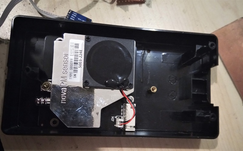
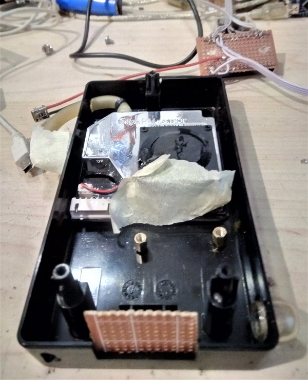
Since I had to order some parts from China, there was not much to do until they came. I was killing some time wondering how to assemble everything together. What will I use as housing? I went through some stuff I had and noticed the old HP Inkjet printer power supply. I opened it and after measuring the size, it looked like everything could fit in nicely. And it did, so this power supply casing was a box for my sensors device.
First I put everything together to see how it works. I had a doubt regarding connecting two i2c sensors in parallel (doubt was about addressing not about can it work or not). BME280 and BH1750 are both connected to scl and sda pins of ESP, and I did not now will Tasmota firmware be able to discover them both without fine tuning. But it worked like the charm from the start.
Wiring diagram
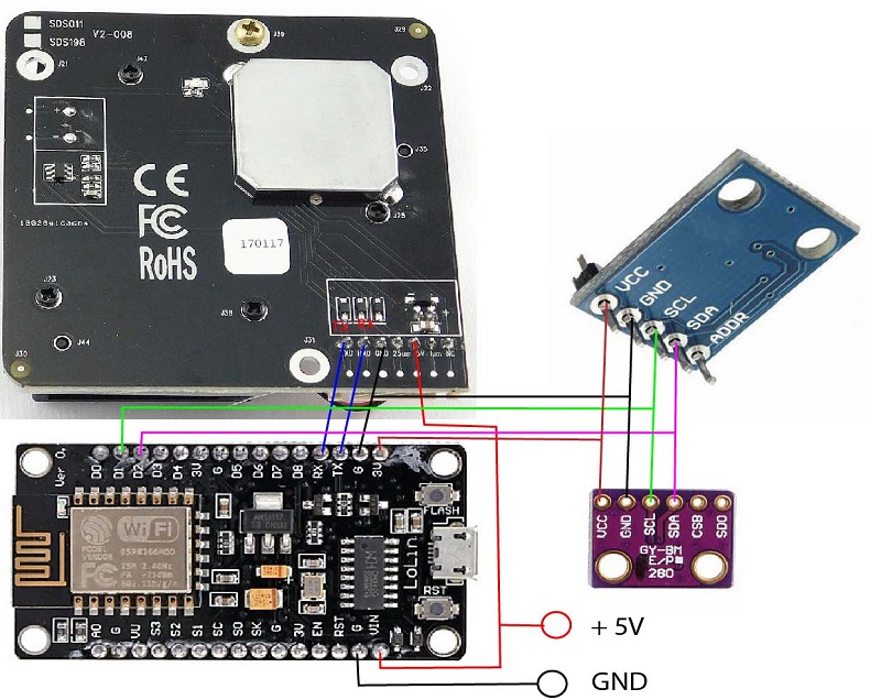
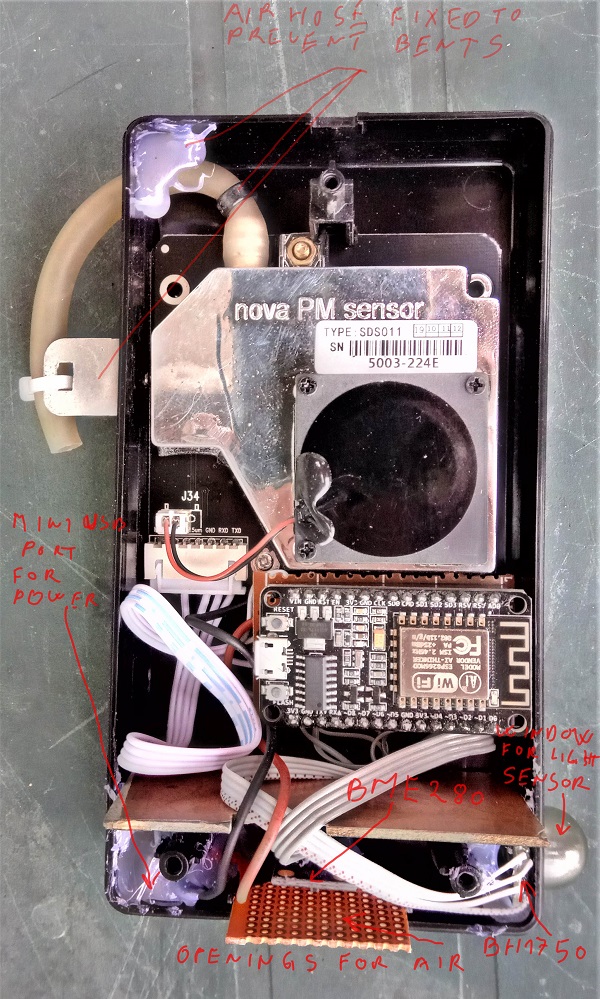
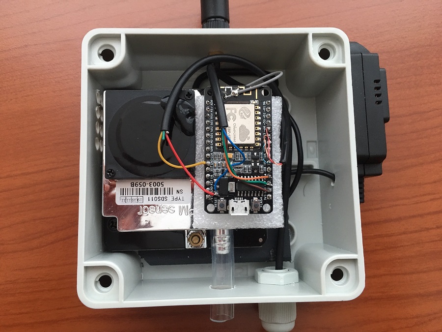
Regarding wiring, SDS011 talks on serial, so RX goes to ESP TX and TX goes to ESP RX. +5 Volt from SDS goes to Vin on ESP with the assumption that you will connect that pin later to the power supply of 5V DC. This sensor working voltage is 4.7 – 5.3 V, so do not connect it to 3 V pin, it is to low and it may affect readings. As always ground goes to ground. BME280 and BH1750 use the I2C bus, so their SCL (Serial Clock) together goes to ESP SCL which is on pin D1, and SDA of both sensors goes to D2 on ESP since it is Serial Data pin. Sensors VCC connects to a 3V pin on ESP. We already know about ground :).
Handling SDS011 while working
Just to mention that it is not a bad idea to cover air inlet and outlet of a sensor while you work around it, especially drilling or grinding, to prevent dirt to pollute sensor. When all rough work is done, remove the covers. Better safe than sorry.
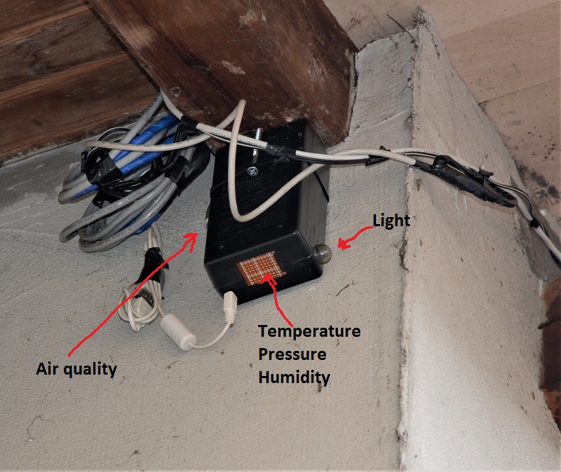
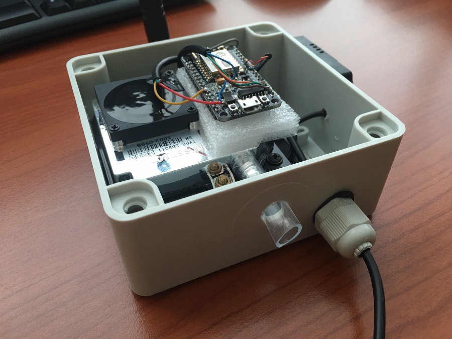
How it fitted together
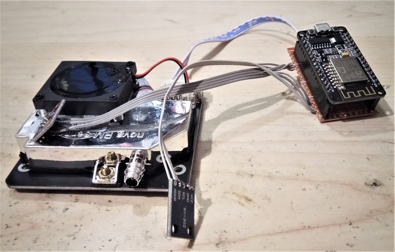
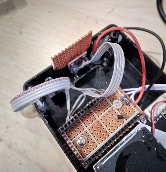
Since the goal was to make it nonexpensive, and yet durable and to finish it fast, this is what I did regarding assembly. I positioned the Nova SDS011 sensor on one side of the box, put a microcontroller next to it and then made some physical barrier to create a compartment for BME280. The reason I wanted it separated was the intention to remove it from any heat dissipation that the ESP8266 board produces no matter how small it is. That way alteration of the temperature reading would be minimized.
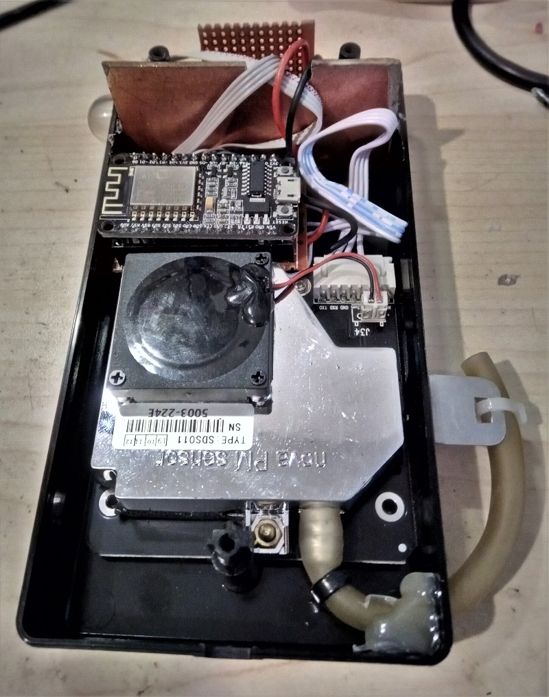
I made a socket for the ESP development board on the prototype PCB, so it can be removed, or replaced easily without any soldering. After all this sensors unit is a prototype. The micro USB connector on the board is accessible when the box is open in case it is needed. There are markings on board so there will not be the accidental wrong insertion of ESP board.
Installation for test measurements
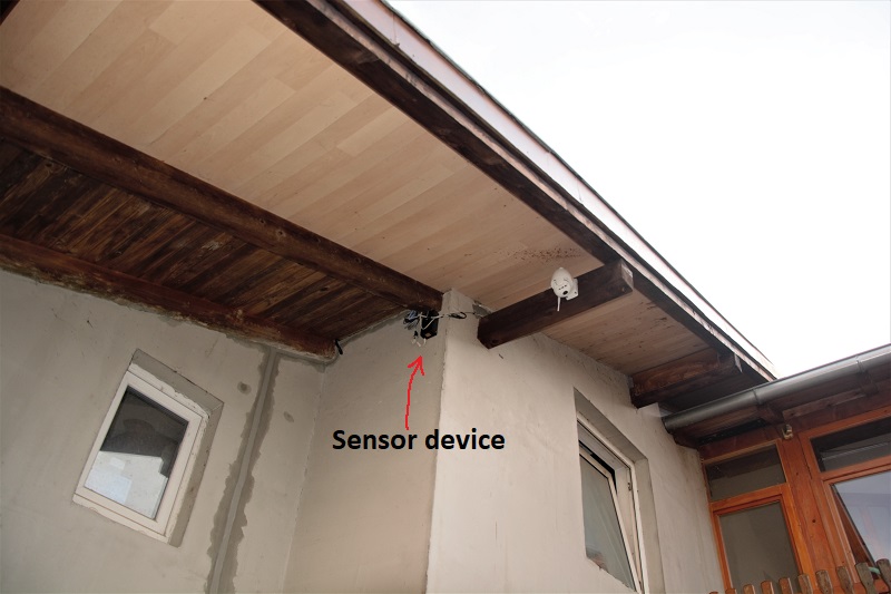
Well, I had the opportunity to dig in some cables since there is still no facade on the house, and I put a few UTP cables in. I used one for PoE camera, other for sensors device power supply, and since this is the IoT time, I left two more cables to wait for it 🙂 . First, I chose this location thinking, that it is high enough from the ground to prevent dust and some other near ground particles to contaminate sensor readings. Second, it is far enough from the roof to have its heat dissipation mess with the temperature readings. Third, it is enough protected from the rain and both air openings are from the bottom so it should be impossible for rain to get into the device or sensors.
Software
Everything built here is a piece of junk without the software.
Tasmota had been flashed on to the ESP. Tasmota will be sending data from sensors to Domoticz. I will not enter into many explanations here, you can find needed information at those two links. I also uploaded flasher and two needed .bin`s here. Firmware is 7.2.0, and it will be obsolete very soon. I put it for those of you that like shortcuts 🙂 . It will do the job, and later you can upgrade.
Flashing ESP with Tasmota firmware
There are literally tons of information regarding the process out there, but I will put it in very short terms again here. 1. Connect ESP to your computer, figure out what com port is it using and configure Tasmota flasher accordingly. 2. Press taster for entering flashing mode and then press the reset taster on the ESP dev. board. 3. Release the reset taster, and then release the first taster on ESP. 4. Select the tasmota-sensors.bin in flasher and then send it to the device. (tasmota-minimal.bin is needed only if you are doing OTA (over the air) upgrade).
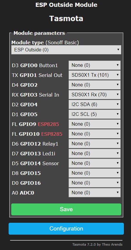
Configure module pins with sensors.
We now need to tell Tasmota, what sensor is connected to which pin on the ESP board. I attached the screenshot of the config and when compared with Wiring diagram it is self-explanatory.
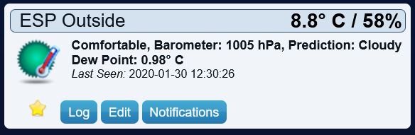
Results from Tasmota and Domoticz
When flashed and configured, here is how Tasmota web interface looks like. You just find its IP address on your dhcp server (it will be showed as sonoff-acb or tasmota-xyz or something like that) and enter that IP address in your browser. It is nice to make a reservation (or static assignment) on dhcp so address stays the same. On that interface you can basically read values from the sensors and configure, backup or upgrade Tasmota.

This is how the results from Domoticz look like.

Temperature humidity barometer virtual sensor 
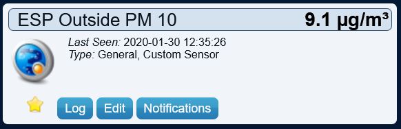
PM 10 virtual sensor 
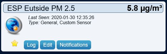
PM 2.5 virtual sensor 
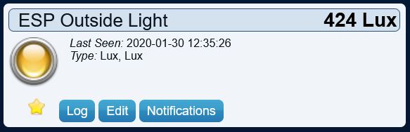
Lux virtual sensor
But it is not just about reading values that came just now, logging gives the real power…

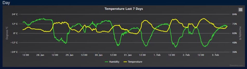
Temperature and humidity week log 
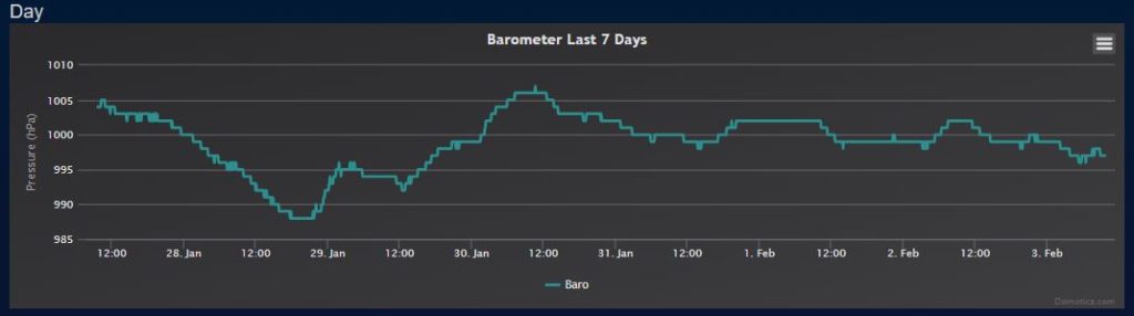
Barometer week log 
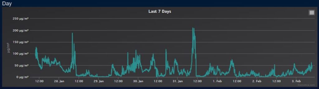
PM 2.5 month log PM 2.5 week log 
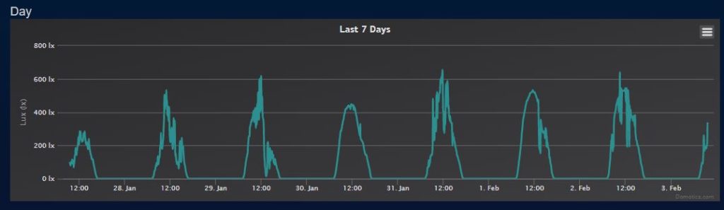
Lux sensor week log
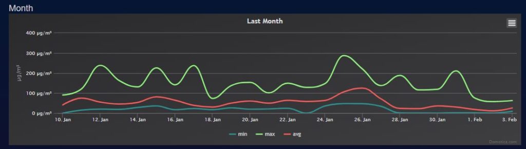
So, from the PM 2.5 monthly shows some real air quality statistics although my sensors unit is still not operational for a full month. One more thing to remember, this shows pollution in PM2.5 μg/m3 (raw) and the usual standard is US EPA PM2.5 AQI. That means if you are going to compare it to “Purple Air” you need to convert, or at change units displayed on Purple air (it is on the map). Anyway these raw readings converted to AQI are much higher, so you know what to expect.
Conclusion
I wrote this with a simple intention. That is to show how easy to build and inexpensive this kind of sensors unit can be. I hope it serves as a warning and a manual.
If you find this article interesting maybe you should check on this one regarding fixing a “weather unknown” message. Once again, thank you for reading, and if you have any questions or need help, just post a comment. I’ll get in touch with you asap.

Here is a little update on Jully 2020. , a friend send me a few pics of his “do it fast” sensors station. He even added external Wi-Fi antenna for a better connection range.

4 comments
What a great post/manual. All components are ordered, so now I have to start looking for my enclosure as well. Maybe I’ll print one.
Do you upload data to WU, Accu or apicn? If so, is that the standard procedure?
Thanx for reaching out Willem. I just updated the post with few pics that a friend sent me. He made the station in an under 3$ box he bought in an electric\electronic store. It is just big enough and even waterproof (it was waterproof before he cut holes 🙂 ) So maybe you can consider something like that for your project. Printing is also a great idea, that way you can really customize everything. I still did not start publishing data to Accu or similar service, I just log it to my Domoticz. To be honest I did not have time. If you do it make some notes, we can publish it here. And when you complete your station please send a few pics, it would be great to have them here. Cheers
Pictures look great! I will figure out the posting to WU or Accu and make some notes about it.
Great, can`t wait to read it.