

Hi,
we would like to share with you some knowledge and experience about the home microcontroller playground.
Arduino microcontrollers will be in focus.
First of all, let’s start by asking ourselves, what is a microcontroller and why do we need it? Someone would even ask does it have anything to do with Microsoft? 🙂 (Just kidding 🙂 )
So here is a basic and simplified definition from Wikipedia:
A microcontroller (or MCU, short for microcontroller unit) is a small computer (SoC) on a single integrated circuit containing a processor core, memory, and programmable input/output peripherals. Program memory is also often included on-chip, as well as a typically small amount of RAM. Microcontrollers are designed for embedded applications, in contrast to the microprocessors used in personal computers or other general-purpose applications consisting of various discrete chips.
So, let`s take a look at few most common used MCU boards:
First, we will speak a little bit about Arduino Nano:
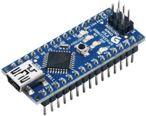
Arduino Nano
Its dimensions are around 4.5 x 1.6 cm 1.8″ x 0.62″ and power consumption at 7 V is 20 mA, so small measures make it perfect for small consumption sensitive applications (Weather station that runs on batteries or solar power or something like that) and price of approximately 2.5 $ makes it great choice for a small hobby projects.
| Name | Processor | Operating/Input Voltage | CPU Speed | Analog In/Out | Digital IO/PWM | EEPROM [kB] | SRAM [kB] | Flash [kB] | USB | UART |
| Nano | ATmega168 ATmega328P | 5 V / 7-9 V | 16 MHz | 8/0 | 14/6 | 0.512 1 | 1 2 | 16 32 | Mini | 1 |
Now let us explain some of this stuff:
Processor
ATmega168
ATmega328P
This means that this board is in the manufacturing process with two processor types, and depending on that there may be more variations between those two boards (clock speed, amount of memory, etc.) If any of this may be important to you watch out what version of the board do you buy since there can be a price difference too.
Operating/Input
Voltage
5 V / 7-9 V
It means that microcontroller works on 5 V (when you connect the board to your computer USB port it will get power also and start working) and when you supply it with external power it should be 7-9 V.
This is because this board has its own voltage regulator and it needs some voltage difference to let`s say make it work as it should or to stabilize the voltage at 5 V.This is also its logic level.
(Remember that with these boards we always talk about DC current).
Analog In/Out
8/0
A number of analog Inputs and Outputs, it is number of pins that you can connect analog signal to. In this case, it means 8 analog inputs and 0 outputs. Why do we need that some may ask?
Let us try to make it as simple as possible, microprocessor works with digital signals, it is it`s an advantage , and now we want to process some analog signals, how is that possible?
Well MCU has some analog to digital converters built-in, sometimes referred to us as ADC, and what they do is convert an analog signal or voltage on a pin to a digital value or a number. By converting from the analog to the digital, we can begin to process analog information’s in our programming and later make some decisions or actions based on this same info.
The main parameter of ADC is its resolution and it is measured in bits. Generally, Arduino ADC is 10 bit, and it means that it can detect 1024 different analog levels it is (210) More bits means better resolution. So if an ADC is 5 V logic level, it means that 5 V on the input pin would equal 1023 read value.
Or put it in formula Resolution of ADC\system voltage = ADC reading \ analog voltage measured.
The logical goal at this moment would be to find ADC reading, and that would be 1023\5 *analog voltage measured. For example, if we have 3.4 volts on analog input, the digital read would be 1023\5*3.66 and that is 750. So now you know in this particular case that voltage of 3.66 volts equals 750 digital read signal. So…. what would we need that information? Imagine that you want to monitor the status of a battery and if it gets to low you want charging to be activated. let’s say that this voltage trigger is 3.6 V or as we calculated 750. Now let’s make a statement that something called x is 750. To put it in most simple words you would write in your microcontroller program something like this: if x<750 turns on relay 1. (Let`s imagine that relay1 activates battery charger). This is just a simplified explanation, not a coding language, but it is not much more different than that.
Now, someone would ask, but what if we want to measure car battery voltage, that should be around 12 V, and in the last example, we can notice that the biggest measuring voltage can be 5 V. Well, that would be great observation, but there is a play around it :). It is called voltage divider but we will come to it later.
Digital IO/PWM
14/6, in this case, it means that this board has 14 digital inputs or outputs, of which 6 can be PWM outputs. Huh, what are you talking about here? Are they inputs or outputs? And what is that PWM???
Ok, let’s start one by one…
If it says 16 digital Inputs/outputs it means that every one of those pins can be either input or output, digital of course. So how do you make it one or the other way? Let’s presume that we want to connect LED to pin digital 3 on Arduino and to turn it on from time to time, or to make it blink. The simple conclusion is that current will flow from Arduino to LED so the Arduino pin is output.
In coding language it would be like this:
int ledPin = 3;
pinMode(ledPin, OUTPUT)
So what we did, first of all, we said that something that we will call ledPin is on digital pin 3 of Arduino board and that we said that it is going to be output. Quite cool, isn`t it?
We could call it John`sPin or Laker`sPin, or KlingonPin, but we would like to know what is it for, so we should have some naming convention established, but this is enough for now since we still do not know what is that PWM and what is it for?
Here we will not reinvent the wheel, but here is just a definition from arduino.cc (your favorite site from now on 🙂 ) :
“Pulse Width Modulation, or PWM, is a technique for getting analog results with digital means. Digital control is used to create a square wave, a signal switched between on and off. This on-off pattern can simulate voltages in between full-on (5 Volts) and off (0 Volts) by changing the portion of the time the signal spends on versus the time that the signal spends off. The duration of “on time” is called the pulse width. To get varying analog values, you change or modulate, that pulse width. If you repeat this on-off pattern fast enough with an LED, for example, the result is as if the signal is a steady voltage between 0 and 5v controlling the brightness of the LED.”
PWM
This is an example of how the PWM signal would look like on the Oscilloscope.
But why is it so important, if we would only like to control the brightness of LED I could use resistors or a trimmer, it is more simple….. well maybe but what if I would like to control a big DC motor? The answer is PWM is your type of signal :). The example of using PWM for controlling the speed and power of the DC motor is a cordless drill. There you have one small PWM regulator, and more you press that start button below your finger more speed and power your drill delivers, and if you would put an oscilloscope on motor terminals you would see signal like on the picture above, going from top when drill is off to bottom as button is fully pressed.
EEPROM [kB]
0.512
1
The microcontroller has EEPROM (Electrically Erasable Programmable Read-Only Memory) and it is a memory whose values are kept when the board is turned off (like a tiny hard drive).
For now, let`s say that this is not something that would consider you on an everyday basis, but if you want to know more about the subject, Mr. John Boxall has greatly explained it here:
http://tronixstuff.com/2011/03/16/tutorial-your-arduinos-inbuilt-eeprom/
SRAM [kB]
1
2
Hm…. you did not read carefully didn`t you? 🙂 Why 1, and 2 kB? Of course, two versions of the board , two different microcontrollers, and a different amount of memory. If you expect to have memory problems, watch over it (of course who would expect memory problems at the beginning of a project 🙂 ). To put it simple bigger the number = better for you.
What is it for?
SRAM (static random access memory) is where the sketch creates and manipulates variables when it runs. Again, the bigger the sketch = more memory to keep it running.
Intruder alert: .. what is a sketch?
The sketch is basically Arduino program. It is a peace of code that is uploaded to, and run on the Arduino board.
These days it has a .ino extension and is produced by Arduino IDE.
Let’s continue, next is Flash memory:
16
32
Again two different boards issue…
Flash memory (program space), is memory space where the Arduino sketch is stored.
More memory = better for you = bigger sketch can be stored.
USB
Mini
Type of USB connector onboard.
UART
1
The native serial support happens via a piece of hardware (built into the chip) called a UART (Universal asynchronous receiver/transmitter).
This hardware allows the Atmega chip to receive serial communication even while working on other tasks.
So basically it is a hardware serial port. This particular board has only one, and you may want to keep those two pins free, or you may end up with problem uploading sketch to a board or using the serial monitor. There is also software serial, and for some applications, it can be used, but generally, baud rate should be kept low (9600) or errors may appear.
So this concludes explaining some basic terms, facts, and features of the microcontroller board. Let us now continue with introducing a few of our favorite MCU`s
Next is our well known may be the most common board Arduino UNO
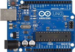
Arduino Uno
It`s dimensions are around 7 x 5.5 cm or 2.7″ x 2.2″ and power consumption at 7 V is 20 mA 50 mA @ 7V and it`s price is about 4 $. We often say around since there are many different versions of the same board and this information is just for you to get the idea of sizes. This board is the most common beginner’s choice, great for many projects, very well documented, many examples, many Shields.
Did we just say, Shields? What is the shield? Do we need some kind of protection from this MCU stuff? 🙂
Again, not to reinvent the hot water here is official Arduino definition: “Shields are boards that can be plugged on top of the Arduino PCB extending its capabilities. The different shields follow the same philosophy as the original toolkit: they are easy to mount and cheap to produce”. If you are interested, a complete list of both official and unofficial shields can be found here: http://shieldlist.org/
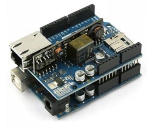
Uno with Ethernet shield
Here is a picture of Arduino Uno with Ethernet shield plugged on top. Ethernet shield as it would sound logical gives networking capabilities to Arduino. For example, you could run a web server on your Arduino, and post some data on it, or even make it so that you can turn on / off some relays through a web page, or transmit some sensor readings to services like thingspeak, or dweet.io .
Not to wander off again, here are specs of UNO:
| Name | Processor | Operating/Input Voltage | CPU Speed | Analog In/Out | Digital IO/PWM | EEPROM [kB] | SRAM [kB] | Flash [kB] | USB | UART |
| Uno | ATmega328P | 5 V / 7-12 V | 16 MHz | 6/0 | 14/6 | 1 | 2 | 32 | Regular | 1 |
Now it`s time to move on and next on our list is Arduino DUE
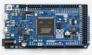
Arduino Due
It`s dimensions are around 10.2 x 5.5 cm or 4″ x 2.1″ . Power consumption when running code is still unknown but will be tested and published soon. The price of a 15 $ makes it a little more expensive, but hey it is one of the most powerful Arduinos these days, so maybe it`s worth considering it as a choice for your next project.
There is one more very important thing to consider about DUE: Its logic level is 3.3 V so take care, if it`s gonna “talk” with some other devices, make sure that they are also at 3.3 Volts ll or you may end up with burned or at least damaged Arduino. The same goes for sensors, shields, etc. . On the other hand, you can mitigate that problem by using logic level converters, but that is another story, for now, let`s try to keep things as simple as possible.
But wait, did we few sentences before, just mention sensors? What about sensors? What kind of sensors? Well, that is the beauty, all kind of sensors are there for MCU`s and especially Arduino…
Let`s first observe DUE`s specs, and then we will return to the sensor story.
| Name | Processor | Operating/Input Voltage | CPU Speed | Analog In/Out | Digital IO/PWM | EEPROM [kB] | SRAM [kB] | Flash [kB] | USB | UART |
| Due | ATSAM3X8E | 3.3 V / 7-12 V | 84 MHz | 12/2 | 54/12 | – | 96 | 512 | 2 Micro | 4 |
If we compare it to Uno we see a dramatic increase in everything, CPU speed, nobler of both analog and digital inputs, some analog outputs, more ram and flash, more UART`s, and of course it is not 5 but 3.3 volts logic level. This particular board is a real small little IOPS (inputs-outputs) monster. It can interconnect with the whole bunch of sensors, relays, and other things, and it has the juice to process them. Great board for almost any kind of project, but keep in mind that it is 3.3 V operating voltage.
Now back to sensors, let’s make it a little more imaginable, what sensors are, and what they do…
A sensor is a device that detects and responds to some type of input from the physical environment. The specific input could be light, heat, motion, moisture, pressure, voltage, current, sound, weight, or anyone of a great number of other environmental phenomena. Some sensors are only able to detect the change, but some are able to even measure that change very precisely.
Here are pictures and descriptions of some of our favorite sensors:
MQ-2 sensor:
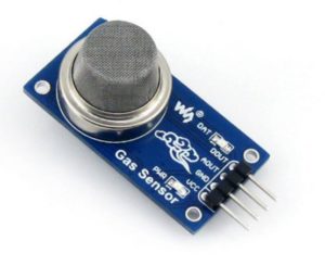
MQ-2
This sensor is able to detect flammable and combustible gasses like Methane, Butane, LPG, and smoke.It may be great for a home fire/gas warning/alarm system.
The price is about 1.5 $.
MQ-7 sensor:
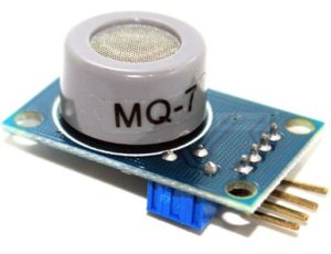
MQ-7
This sensor is able to detect Carbon Monoxide, so in combination with MQ-2, you get a great early warning gas detection system.
One more thing to address here, there is a common myth that Carbon Monoxide is heavier than air. Whoever says that is wrong! CO has a molar mass of 28.0, and air has an average molar mass of 28.8, so it is, in fact, a little easier. It can be assumed that weight of air and CO is the same, and since CO is usually produced from incomplete combustion (heat source), it can be also assumed that CO will move in direction of hotter air, and warm air is more buoyant than cold air so it rises. Following this logic and fact that CO is lighter than the air I would personally put my CO detector on higher place or at the ceiling near the heat source. One more thing CO is odorless, colorless and tasteless, so without the detector it is impossible to notice, that is why it is called “silent killer” and that nickname is well earned. So, MCU`s can even save your life sometimes……
The price of the MQ-7 is about 1.6 $.
Back to sensors…
Dallas DS18B20 temperature sensor:
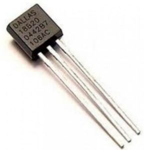
DS18B20
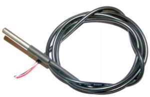
DS18B20 waterproof
It measures temperature in 9-12 bit values (0.5 deg precision) in range of -55°C to +125 Celsius degrees (-67 °F to 257°F)
It comes in two forms, or packages: TO-92 casing (not waterproof, good for measuring air temperature) on the left picture, and Etanche or Waterproof casing, on the right picture.
These sensors are easy to use, connect and read. Multiple sensors can be connected to the same input since they each have hardware addresses burned in. If you are gonna use a few sensors, like 2 or 3 and have enough inputs free on your MCU, use separate input pin for every Dallas sensor, it is easier since you do not have to read hardware addresses of sensors, and then target them to read data. The waterproof version is great for measuring the temperature of liquids, and other things and places where to-92 would be impractical or on the harm’s way. It can be connected to MCU with 2 or 3 wires, both ways work well, and fewer wires mean more simple and practical, so take your pick.
The price of DS18B20 is less than 1 $ for the TO-92 version, and about 4 $ for waterproof version.
DHT11 Temperature and humidity sensor:
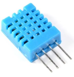
DHT11
It is something like a combination of DS18B20 and humidity sensor. Humidity measurement range: 20% – 95%, temperature measurement range 0 degrees-50 °C . Humidity measurement error: +-5% ,
temperature measurement error: +-2 degrees. Great for hobby weather station projects. Its successor is DHT22 better range and more precise.
The price of DHT11 these days is about 1 $.
Soil Humidity Hygrometer sensor:
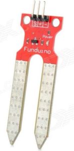
Soil Humidity Hygrometer sensor
The name of this sensor says enough. Why would we use it? Well, with this sensor stuck in-ground, MCU could “know” was or is their rain, and how dry or wet is soil, and based on that turn on or off the irrigation system.
The price of this sensor is below 1 $.
Infrared PIR Motion sensor:
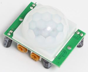
PIR Motion
Motion detection sensor, great add for a homemade alarm system.
The price of this sensor is around 1 $.
Ultrasonic Module sensor :
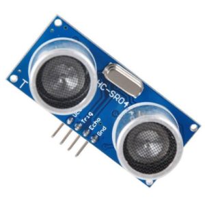
HC-SR04
This sensor can measure distance in the range of 2 – 500 cm by the precision of 3 millimeters. Great add on for DIY robots or smart cars.
The price of this sensor is around 1.2 $.
Single Phase Voltage sensor :
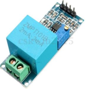
Single Phase Voltage
Monitor your mains voltage, for example, you can make MCU send a signal for the generator to start if the voltage goes below or above nominal value.
The price of this sensor is around 5 $.
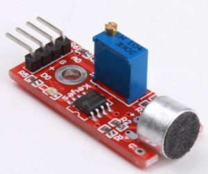
Microphone
Microphone sensor
This sensor can identify the presence or absence of sound, based on that your MCU can make some actions, for example, if there is a sound detected, turn on light.
The price of this sensor is around 1 $.
Light sensor :
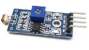
Light
This sensor can detect light intensity. Based on this information your MCU can activate something else, for example, if it is a daytime do not turn on the watering system.
The price of this sensor is around 1 $.
Vibration switch sensor :
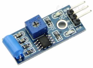
Vibration switch
This sensor is used to trigger the effect of various vibration, theft alarm, intelligent car, earthquake alarm, motorcycle alarm, etc.
The price of this sensor is around 1 $.
So, to conclude the story of sensors we can make the next conclusions:
- There are many many different types of sensors (light, sound, distance, voltage, motion, vibration, gas, temperature, moisture and many, many more).
- Sensors are quite inexpensive.
- A combination of different sensors can give your MCU interesting possibilities and decision-making information.
So sensors are great, and they can make our MCU playground even bigger and more interesting and productive.
It`s time again to move on and next on our list is Arduino MEGA
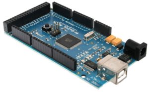
Arduino MEGA
This is maybe the most commonly used and best money\features ratio Arduino board.
Its dimensions are the same as a DUE board or around 10.2 x 5.5 cm or 4″ x 2.1″. Power consumption when running code is still unknown but will be tested and published soon.
With price about 8$ whole bunch of In`s and out`s and decent memory and clock speed it is great for many applications and there is even an open-source 3D printer driven by MEGA.
If we compare it to DUE, it has the almost the same number of ports, slower processor and less memory, but it is a 5V board, so if you are gonna deal with 5V signals, chose this one. There are also different versions of this board, so less money does not necessary mean that you got a better deal. This is applied for all MCU boards since there is a big difference in quality from components used to soldering. There is also a whole mess about different markings, but for the most part, it is a marketing trick. You have Arduino Mega ADK (stand for Android development kit), then you have Arduino Mega 2560 but for the most part, those are the same boards.
| Name | Processor | Operating/Input Voltage | CPU Speed | Analog In/Out | Digital IO/PWM | EEPROM [kB] | SRAM [kB] | Flash [kB] | USB | UART |
| Mega 2560 or Mega ADK | ATmega2560 | 5 V / 7-12 V | 16 MHz | 16/0 | 54/15 | 4 | 8 | 256 | Regular | 4 |
Now let`s observe some non-Arduino boards…
ESP8266 :
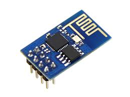
ESP 8266 v1
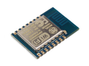
ESP 8266 v7
Two different versions, version 01 on the left and version 07 on the right.
The ESP8266 is a low-cost Wi-Fi chip with full TCP/IP stack and microcontroller capability produced by Shanghai-based Chinese manufacturer, Espressif.
But what makes it so interesting? It has Wi-Fi but is also a microcontroller. So what? So you can use it in different ways, for example, it can work as a Wi-Fi interface for other MCU (like Arduino). In this case, it will transmit some data that another MCU gives it, over serial connection through Wi-Fi to LAN or to the Internet. It can also host a web server and present data to it. But I think that that was not in mind of designers od 8266. It is quite equipped to work as standalone MCU.
Here is manufactures general specs:
- 802.11 b/g/n
- Serial/UART baud rate: 115200 bps
- Integrated TCP/IP protocol stack
- Input power: 3.3V
- I/O voltage tolerance: 3.6V Max
- Regular operation current draw: ~70mA
- Peak operating current draw: ~300mA
- Power down leakage current: <10µA
- +19.5dBm output in 802.11b mode
- Flash Memory Size: 1MB (8Mbit)
- WiFi security modes: WPA, WPA2
- Module’s dimensions: 24.75mm x 14.5mm (0.974″ x 0.571″)
- The CPU clock is 80 MHz
- Number of GPIO`s depends on a board version
Yes we just said GPIO, so let’s explain it:
General-purpose input/output (GPIO) is a generic pin on an integrated circuit whose behavior—including whether it is an input or output pin—is controllable by the user at run time. GPIO pins have no predefined purpose and go unused by default. It is something like Arduino in`s and out`s. This little piece made an entire revolution on IoT playground, and we will not even try to go deep into a story about ESP8266 since there is so much blog posts, guides, Instructables, even whole blogs dedicated to it.
Thing is if you are gonna start playing with ESP, then you will soon learn what the hell is :). Why?
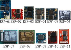
Bunch of ESPs
And even not all of them are here 🙂
But that is not all, you have also different command processors, for them. In the original version, they come with AT cp (those of you that remember dial-up times will know AT commands ), but there are also NodeMCU some others. We will soon write more details about ESP, to get you started…
Word of the author:
Well, it is time to end this story, I hope you find it useful, interesting, and if you have any comments, thoughts, or simply want me to test something, please leave a comment and we will get in touch.
Once again thank you for reading.

🙂
6 comments
You really saved my skin with this inorfmation. Thanks!
We are glad it helped you, thank you for reading, soon there will be more.
Oui eh bien!
tennilleet
Hi, Neat post. There’s a problem together with your site in internet explorer, would check this… IE nonetheless is the market chief and a big section of people will pass over your great writing due to this problem.
I must say you have hi quality articles here.
Hi it’s me, I am also visiting this website daily, this
web site is really fastidious and the people are truly sharing good
thoughts.